The T440 is a lower cost RS232 remote controller for LCD and DLP video and data projectors, LCD and Plasma flat panels, for budget installations in lecture theatres, classrooms, churches or conference rooms.
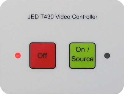
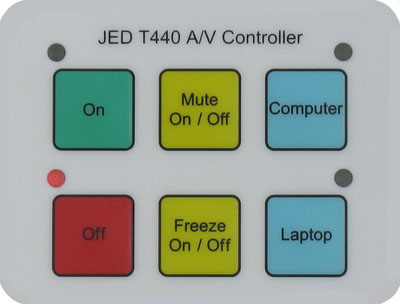
It uses LEDs to show system status, and has a variety of keyboard options with either two, four, six or eight keys.
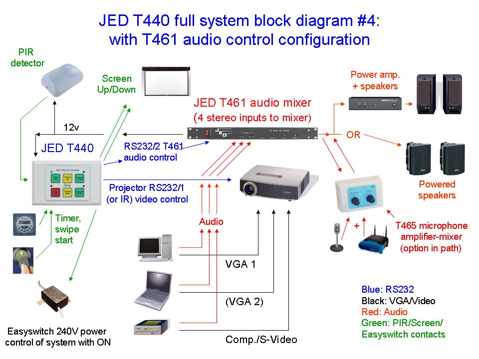
The JED T440 projector controller (and optional T441 or T461 audio controller) offers a convenient system to control video and data projectors from a suitable point on a lectern, bench or wall near a speaker's location in a hall or theatre.
The T440 has an attractive white, black or metallic smooth escutcheon surrounding it, to give an overall size of 117mm by 76mm. This covers the screw holes and can be mounted into a lectern or desk at a convenient point for the speaker to control video and data projector operations.
The T440 is wired to the LCD projector or flat panel via a three wire RS232 data cable, using TX, RX and Ground.
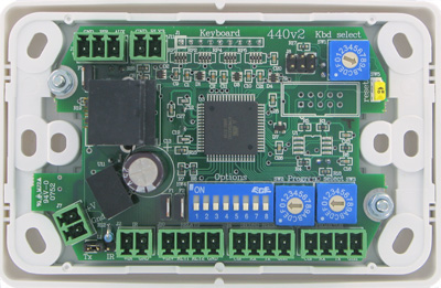
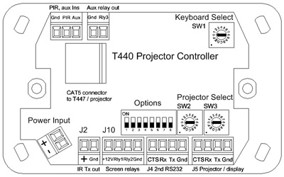
The control codes for different projectors are programmed into the T440 controller, and are selected on the two rotary switches on the back. Keyboard type and options are selected on other switches on the back.
Keyboards
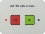
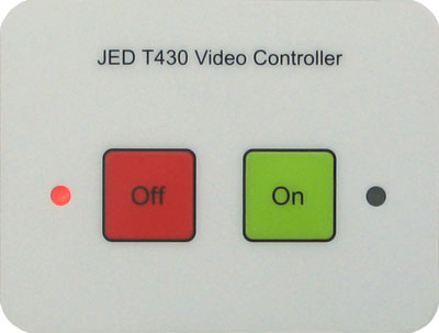
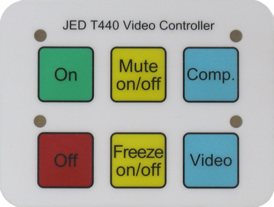
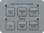
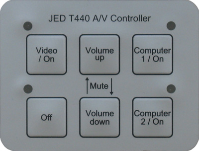
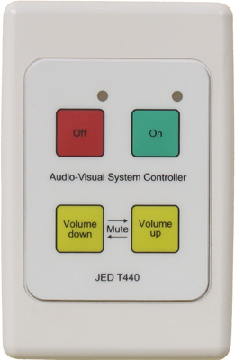
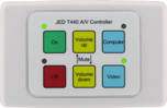
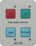
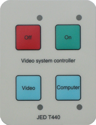
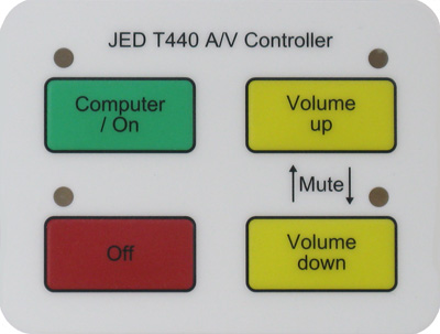
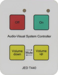
The normal keyboard background colour is off-white, or "beige", as the photos show. Other colours and key layouts can be produced if a quantity are needed.
The CodeBL-Metal is the second option: this comes with a darker "liquid metal" surround ... the same matt metallic finish used by European auto companies for interior fittings. Looks great in boardrooms!
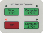
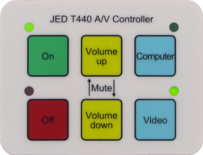
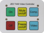
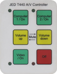
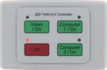
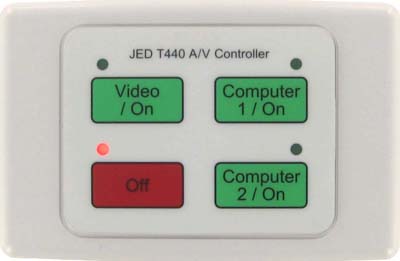
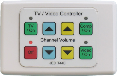
The T440 has a choice of keyboard labels (shown in the right sidebar on this page) ... many different layouts can be accommodated, with up to eight keys. Two are "portrait", the rest are "landscape".
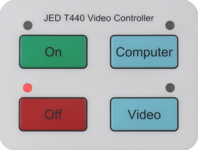
In some layouts, a separate On and Off keys are provided, having green and red LEDs as state indictors. During warmup the green On LED flashes. During cooldown, the red Off LED flashes. A channel LED comes on steady to indicate the channel to start with after warm-up. (Other sources can be pre-selected.)
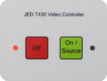
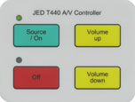
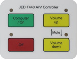
In layouts which combine a channel button with the "On" function, the selected channel LED flashes during warmup. (Other sources can be pre-selected.)
Keyboard "double-press" mode
Keyboards with a single computer key or a single video key are able to select alternate video or computer channels by setting the OPT4 switch on the back. (The primary channels are selected when first switching from Computer to Video (or after startup), and a second press toggles to the alternate channels.)
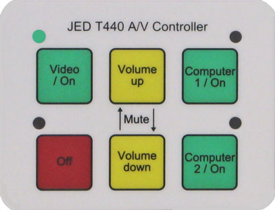
Audio mute function
Pressing both Volume keys together mutes the sound and picture on most projectors (some don't have support for this).
(Either yellow key, or the current channel key, restores the picture/sound).
The audio keys auto Increment/Decrement the audio level if a yellow key is held down. (Times are programmable.)
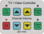
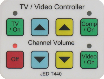
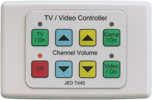
Keyboard for TV control
The Code-E keyboard (see right) is a control panel for LCD or Plasma TV, which adds a Channel Up/Down to the other functions.
Audio control
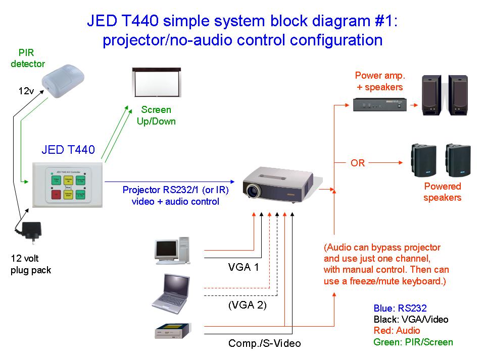
The control of audio level is usually done in the projector, and audio control signals are sent to the projector along with the video and power control signals.
This assumes:
The projector has enough, and appropriate, audio input connectors for the video & computer channels to be used;
There is a line level audio output connector on the projector to drive the room amplifier and speakers; and
The projector actually controls the audio level of the output audio via RS232 (not just the projector's internal tiny speakers).
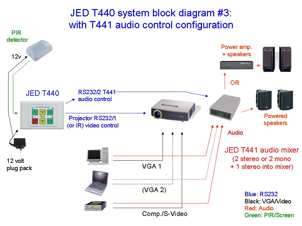
If all of these three are NOT true, you will need an external audio controller, e.g. the JED T441 or T461 to control the audio. Setting Option8 DIP switch selects external audio control mode. See JED Audio devices. (There is also a driver for the DPA22 two-channel stereo audio amp/mixer.
If an external audio controller is installed, it is controlled with the second serial port on the T440, and the controller selects and controls the audio levels in step with video "source select" signals sent to the video projector.
Application
The simplicity of operation of the T440 is its major advantage when installed in locations where a number of users/teachers/lecturers who are unfamiliar with A/V equipment, and without an audio/visual assistant/operator, need to run a "show".
They need to power up the projector, select a source, run a video or computer presentation or demonstrate some other program, or display a feed from a document or microscope camera on the video screen, and then close the system down again. Contrast the four or six buttons on this unit with the 20 or 30 on some IR remote controls, each one different from room to room. This unit is identical from room to room, even with a mix of different projectors.
And when the show is over, T440 controller does not walk out the door in the lecturer's pocket like IR remote controllers often do!
Operation
The operation of the T440 is very logical:
Turn the system on by pressing the/an ON key. The projector starts, and a green LED blinks for the warm-up time ;
If a different source is needed, press an alternate source key until the desired source LED turns on;
When running, use the yellow VOLUME UP and VOLUME DOWN keys to set the desired audio level for that source. In absolute source volume systems, or, in systems using the JED T441/T461 audio attenuator/mixers, the last used setting is remembered and restored.
Pressing both volume keys together causes a picture/sound mute;
(Alternate layouts, may have mute or freeze key rather than volume keys);
When the show is finished, pressing the OFF key ramps the audio down and turns off the projector. The red Off LED flashes for the cooldown period.
The proper warm-up and cool-down and lockout times are set for the projector, until the unit goes to standby mode for the next cycle.
Pressing the OFF key in the standby mode will re-poll the projector, and if the projector communications is responding, the red LED with blink once. If there is no communications, the red LED with blink three times. (If there is no blink at all, it is because that particular projector has no readback of status on OFF mode, or no feedback at all, i.e. the IR controlled projectors.)
PIR input for automatic closedown
The relay contact from a PIR (Passive InfraRed) detector in the room is sensed by a T440. This can be used for a reset of a time-out on the projector power, so that while people are in the vicinity, the projector keeps running until manually turned off. Users can set a time-out period after which the projector automatically powers down if no activity is detected on the keyboard or via the PIR. The Run-time is adjustable from zero (disabled) to sixteen hours. (Default is 30 min.)
This option is intended for classrooms and theatres where manual turnoff might be missed, to save lamp hours.
Auxiliary input for timer and external start switch
There is an extra input which can be programmed to receive contact commands from a timer or user-start switch. See Timer: Ancillary page
Screen relay output
Two N-FETs provide contact closure to ground as solid-state "relays" for screen control. The connector has a ground connection and a +12 volt output as well.
The default protocol is one 2-second closure on the "down" contact after an "ON" button is pressed, and an equivalent 2-second closure on the "up" contact after the "OFF" button is pressed. (This is compatible with most electric screens sold in Australia, e.g. the ones from ScreenTechnics).
(Longer pulses timed by the "warm-up" and "cool-down" timers can be generated for screens that need timed Up and Down times, and another option allows for screens which assume a contact close indicates "screen-down" and the same contact opening indicates "screen-up".)
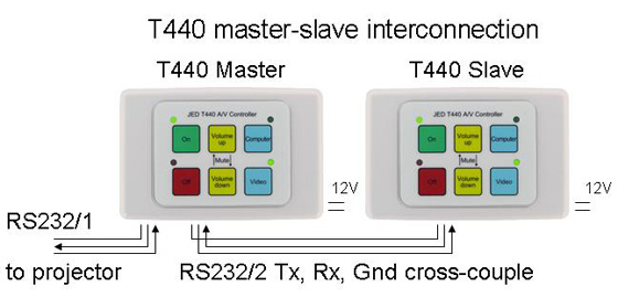
Master / Slave Interconnection
Two T440s (any key code, but must both be the same) can be interconnected so they provide two control locations, say, in a hall, church or theatre. One could be up at the stage or lectern, and the second one back in an A/V control room or desk. Both units can do all functions (On, Off, Source, Volume or Mute/Freeze) and all status LEDs are duplicated between units. The user's manual describes the wiring and setup required (Page 18, Part A.)
Installation
The wiring for the T440 system is very straightforward:
Mount the T440 in or on a panel or Clipsal 2000 base on the wall;
Wire a supplied 12 volt regulated power supply to the power input socket;
Connect a three wire RS232 cable (TX, RX Ground) to the display device;
If a remote audio attenuator/mixer is needed, wire to this from the second serial port. (Option switch 8 enables separately controlled audio;
Wire the PIR into the T440 3-pin plug, or jumper the PIR input to Gnd if no PIR used, so the timer function operates, if desired;
Wire the screen relays to the screen controller, if desired.
Setup
Setting up the T440 is also very straightforward and done from rear with a small screwdriver.
Note: Every T440 holds all codes for all supported projectors and all flat-panels. (Originally, there are two software loading options, one for "projector" and one for "flat panel". As at release V100 in May 2015, projector and flat panel code sets are combined into one master file, and the user at install time can set Flag-F to pre-select projector codes or flat panel codes to be sent.)
Display devices are selected by just setting the pair of rotary numbered switches (called "Program select") to the specified 2-digit hex family code.
The option DIP switches allow for some special functions, e.g. to automatically send a "pixel align" command after a "computer" channel select or when the computer button is re-pressed. Option switches also allow swapping some computer or video channel allocations, and selection of external audio controller.
The top, single rotary switch is used (in the factory) to set the keyboard code.
Constants can also be setup using a screwdriver to alter channel mapping to keys or alter warmup, cooldown or PIR time-out times or automatic or manual aspect ratio changing or setting. See the user's manual for details
No lap-top based programming is needed ... just a screwdriver!
.
What's inside the T440
The T440 is based on the Atmel ATmega2561 CPU.
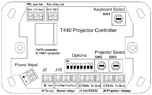
I/O connectors for the T440: Serial
The connection to the display device is a Phoenix plug in screw terminal at the lower, far right end of the back. This RS232 data cable usually needs only three wires (TX, RX and Ground). (A connection for a fourth wire with 9 volts on it is available as a CTS or DTR line HIGH to the projector to enable RS232 transmission, as some projectors expect this input to be HIGH before allowing transmission.)
The next connector (to the left of the display connector) is for external audio controllers, relay boxes like the T462-R2 or -R4, or the USB switchers when used under RS232 control.
Note: JED controllers all use bidirectional RS232 communications with displays and audio boxes, and provide blink codes on the red LED for display communications OK and a flash on the top left green LED for audio/T462 communications OK.
The T440 serial ports are full +/- RS232
levels, not just 0-5 volts as some other controllers only
provide.
I/O connectors for the T440: Relays, PIR and logic
The next 4-pin connector to the (lower) left is the screen relay connection. Two N-FETs provide contact closure to ground as solid-state "relays" for screen control. The connector has a ground connection and a +12 volt output as well. The operating mode of the screen drive and the timing of the screen pulses can all be set using the "Constant" setting procedures to setup nonvolatile memory.
Note: This screen driving interface is NOT suitable for the most recent Somfy
screen controller (anemeo IB+ 1AC) as this uses a
common raised to plus 13.7 volts. The older CD4
controller from Somfy does use a ground-referenced
common, and is fine with this N-FET drive. If using an "animeo" controller, the T462-R2 still provides an isolated
mechanical relay interface. (ScreenTechnics uses ground as the common.) For non-grounded common systems, use a T462-R2 or an isolation relay.
The 12-volt output can be used to power the coil of an isolation relay (or two), or can be used to power the PIR (see next item) or a USB switcher.
Three-pin input connector on top left ... both inputs have pullups to 5 volts and take a contact closure to the Gnd connection:
PIR Input: This input adds a powerful feature to the
T440 … it allows a Passive Infra Red detector to be connected
to the unit. This senses the presence of students
in a classroom, and this is used to control an internal power-down timer.
Auxiliary input: For contact closure-initiated start or Timer-initiated start. (use OPT3 switch to enable.)
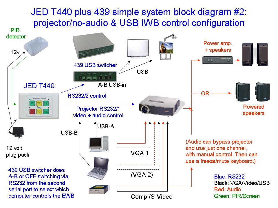
Auxiliary Relay out: By default, this relay closes whenever "Computer 2" source is active ... this is to activate switching to USB input B on a JED 439 USB switching device (so that a teacher's laptop becomes the source of USB control signals to an Interactive Whiteboard instead of the USB-A channel, driven from the teacher's desk computer.
A simple setting of a different number into a constant will re-route the logic behind the Aux. Relay output so that it turns ON when an ON button is pressed, and OFF when the OFF button is pressed. This is to operate a mains-switching relay to turn power on and off of an audio system wired though a relay driven by this output signal. Boolean Engineering makes the EASYswitch for this purpose. (A new version in due for release with IEC sockets rather than cables with lead plug/socket. This is of more use internationally.)
I/O connectors for the T440: IR transmission
The last connector on the lower left edge is a transmitter output to an IR "bug" to drive commands to projectors or displays which have IR control only and no RS232 interface. Currently this supports a range of Epson projectors only, and keyboard "Code 1" is designed to support this mode.
(IR control of displays is usually at a disadvantage compared to RS232 ... usually there are no absolute "On" or "Off" power commands, rather one IR code, "Power", serves for both ON and OFF. Thus the controller has to make assumptions re the state of the projector. Also "Source" commands are limited, and as per the "Code 1" keyboard, there are no absolute source commands, rather the "Source" IR command just moves to the next source in a loop which happens to have an input at that moment.)
I/O connectors for the T440: Power input +12 volts
The DC power input to the T440 controller is the 2-pin Phoenix connector at an angle on the bottom left corner.
Power supply: Power input is rated for 8 to 20 volts …
we recommend a 12v regulated power pack. Current consumption
is under 50mA at 12v.
A T461 audio mixer can
also supply this.
A suitable regulated +12 volt power supply is included to Australian and new Zealand purchasers. See:
I/O connectors for the T440: CAT5 (centre) to the T447 or display
The use of the T447 allows very simple wiring of the T440 A/V control environment: a single CAT5 cable is all that is needed through the wall to the T440 at the operators location. A T447 box is installed up by the projector, and a single pre-terminated CAT5 Type A cable (non-crossover) interconnects the two boxes. See T447.
Then, up at the T447, 12 volt power in, a D9 serial connector to the projector via a patch cable and the PIR connections are all connected via the CAT5 cable to the controller.
The T447 also provides Tx and Rx line LED monitors with pulse stretchers so that signal communications in both directions with the display are shown to installers.
Software for the T440
All JED controllers can be field-upgraded from a lap-top or computer via a serial port, or via a USB to serial converter, to include new device drivers and data-base via a serial cable. Software to do this can be downloaded from a link on the top left of this page, as a windows application. The latest software release is available by request from JED.
Each released version of the software includes all projectors (or flat panels) currently supported. (The "Included projectors" file lists supported devices.)
Other T440 details
Mechanical: The T440 is 117 by 76mm, and uses Australian/NZ standard Clipsal 2000
mountings.


 />
/>
 />
/>