
T455 RS232 serial expander/multiplexer |
|---|
|
|
||||||||||||||||||||||||||||||||||||||||||||||||||||||||||||||||||||
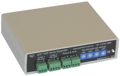
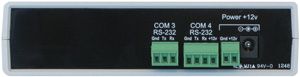
IntroductionThe T455 serial expander allows one master RS232 serial control device to be connected to up to three other RS232 devices, allowing fully buffered bi-directional communications between them. Simple ASCII commands are sent from the master device to the T455 to select which serial port is to be opened for communications. The serial communication parameters of each COM port are easily set via the four hexadecimal rotary switches on the front panel. InstallationA 12V 200mA DC power supply should be connected via the 2 way phoenix screw terminal connector or DC jack. OperationCOM 1 acts as the ‘master’ port, to which all control commands should be sent. Upon sending the correct ASCII control string, one of the other slave COM ports (2-4) will then be opened and remain open allowing transparent bi-directional communications between the two respective COM ports. Commands may also be sent to COM 1 allowing direct control of the onboard relays and FETs. Setting Baud RateThe baud rate setting of each COM port is set using the 4 rotary hex switches on the front panel as shown in figure 1. The switches are only read on power-up or when the ‘reset/load’ button is pushed. The baud rate settings for the rotary switch are shown in table 1 below.
COM 1 COM 2 COM 3 COM 4 
Figure 1
Table 1 Setting ParityThe parity of COM 2-COM 4 may also be set using the rotary hex switches. To do this, simply set the COM 1 rotary switch to ‘F’ and then select a value of 0, 1 or 2 on the COM 2-COM 4 rotary switches to set the parity condition as per table 2 below. Once set it will be stored in non volatile memory and remain even after power is removed.
Table 2 Security access via PINBefore new values can be entered for the above settings, a 4-digit PIN number has to be entered on the switches and the load button pressed. When the setting process is finished, access via the switches can be locked out with a different PIN number. Onboard Relays and FETsThe T455 has two isolated relays and two ground-switching FETs onboard which can be controlled by sending serial commands to the master port COM 1. When a valid relay or FET command is received, the 455 will reply with ‘OK’. The commands for these are listed under ‘Control Strings’ below. Control StringsASCII control commands are sent to the master COM port (COM 1) to open any of the other 3 slave COM ports (COM 2-COM 4). The command format is listed below. A valid command consists of 6 ASCII characters and takes the form: ESC N[c][x] CR LF Table 3 describes the various elements of the command strings:
For JED audio devices, see: JED audio products For JED audio devices, see: JED ancillary devices |
|||||||||||||||||||||||||||||||||||||||||||||||||||||||||||||||||||||